The Facts About Roller Bearing Life CalculationsA Whitepaper from PBC Linear, A Pacific Bearing Company
How to Properly Calculate the Statistical Probability of Lifetime for Linear Roller Bearing Applications
Introduction: Important Notice about Lifetime Calculations
There is no known formula for accurately and reliably calculating the actual lifetime of a linear or rotary bearing system. The formulas within this section are solely based upon the statistical probability of success. It is important to recognize and distinguish between formulas of absolute certainty and probability.
Even though these formulas are not absolutely certain, they have been generally accepted as the best available method for determining bearing lifetime by the International Organization for Standardization (ISO) as well as its membership bodies; including, but not limited to: American National Standards Institute (ANSI), Deutsches Institut für Normung (DIN) & Japanese Industrial Standards Committee (JISC).
Static & Dynamic Load Ratings
PBC Linear uses the two internationally accepted methods for calculating the Rated Lifetime, Static and Dynamic Capacities. Per the international standard, all lifetimes are calculated to an L10 life of 100 km (105 meters or ≈3.94 million inches). The two standards used are:
ISO76 Rolling Bearings – Static Load Ratings ISO281 Rolling Bearings – Dynamic Load Ratings & Rating Life
NOTE: Some suppliers may choose to rate their bearings based upon a useful life of less than 100 km or a probability of success less than 90%. This causes their bearings to falsely appear to have a higher static and dynamic load capacity. If a catalog does not specifically note L10 = 100 km, caution should be used when comparing load capacity or life values between suppliers. The most commonly used values are L10 = 50 km and L25 = 50 km. For comparison, at L10 = 100 km, an example bearing has a maximum static load of 1,000 N. That exact same bearing as an L10 = 50 km maximum static load of ≈2,300 N and an L25 = 50 km maximum static load of ≈4,600 N!
In summary, the static load ratings are defined as the maximum applied load (or moment) which will result in the permanent deformation which does not exceed 1/10,000 of the diameter of the rolling element (ball or rod) within the bearing. The basic dynamic load rating, C, is the load of a constant magnitude and direction which a sufficiently large number of apparently identical bearings can endure for a basic rating life of one million revolutions. It’s important to note that both the static and dynamic values are determined though ISO-Approved formulas. These formulas take into account several factors, including the design, internal geometry, material type, material quality and lubrication type.
NOTE: Additional factors are provided so that the estimated lifetime (default = 100 km) and/or the probability of success (default = 90%) can be changed from their default value to any desired value.
Operating Lifetime
The “Operating Life” (or Operating Lifetime) is the actual life achieved by a rolling bearing. The actual lifetime typically varies from the calculated lifetime, sometimes significantly. It is not possible to accurately and reliably determine the actual Operating Life through calculations due to the large variety of operating and installation conditions. The most reliable method to achieve an approximation is by comparing the current application to similar applications. Primary factors which can negatively affect the life and are generally not included in calculations are:
Contamination within the application Inadequate or improper lubrication Operational conditions different from calculated values, including unexpected forces and moments Insufficient and/or excessive operating clearance between the roller & guideway Excessive interference between roller & guideway (typically due to misalignment or excessive preload) Temperature out of range High shock loads (exceeding static load capacity) Vibration (which causes False Brinelling resulting from Fretting) Short stroke reciprocating motion (also causes False Brinelling) Damage caused during installation or from improper handling Improper mating surface hardness (when not used with a PBC Linear rail)
Terms, Definitions and Symbols
The following variables are used within the equations listed on the following pages.
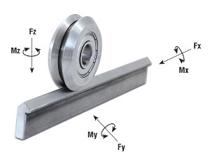
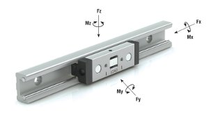
Fy_app = Force applied in the Y direction (radial force), N
Fz_app = Force applied in the Z direction (axial force), N
Mx_app = Moment applied about the X axis,N
My_app = Moment applied about the Y axis,N
Mz_app = Moment applied about the Z axis,N
Fy_max = Maximum allowable force in the Y direction (radial force),N
Fz_max = Maximum allowable force in the Z direction (axial force),N
Mx_max = Maximum allowable moment about the X axis,Nm
My_max = Maximum allowable moment about the Y axis,Nm
Mz_max = Maximum allowable moment about the Z axis,Nm
Da = rolling contact diameter,from product tables,mm
fH = Shaft (rail)hardness reduction factor
fL = Required Lifetime (km) reduction factor
fR = Reliability reduction factor
fSS = Short stroke reduction factor
L10 = Basic rating life, km (103m)
Pr = Equivalent radial (Fy ) load,N
s.f = safety factor
NOTE: PBC has chosen to depart from the nomenclature standards used by ISO. Instead, PBC has chosen to use a convention which is more in line with other PBC products. This ensures that all PBC products use the same naming conventions, making it easier to compare multiple products from different product families.
Derivation
The lifetime formula within ISO 281 gives the life in millions of revolutions. The conversion from rotary life to linear life is done using the conversion factors listed in the following three equations. This derivation applies to both individual rollers and carriages. Lrev and Ldistance represent the lifetime of the bearing in revolutions and linear distance, respectively.
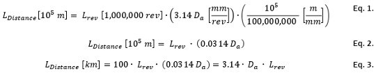
NOTE: Attention must be paid to units of measure, especially when considering products from different manufacturers. All of the lifetime formulas within this section yield results in kilometers; however, not all companies follow the same standard. Some companies may express life in meters or 100s of kilometers.
Individual Rollers – All products except Hevi-Rail Rollers
(see next section for Hevi-Rail Rollers)
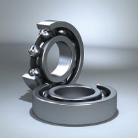
Most of the individual rollers within this catalog are Radial Ball Bearings. The following formulas should be used for all individual bearings except Hevi-Rail bearings (which are roller bearings). This formula calculates the basic rating life (L10 life), which does not take into account any reduction factors based upon the application.
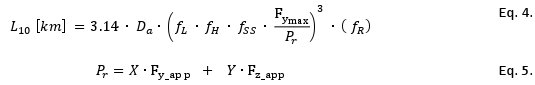
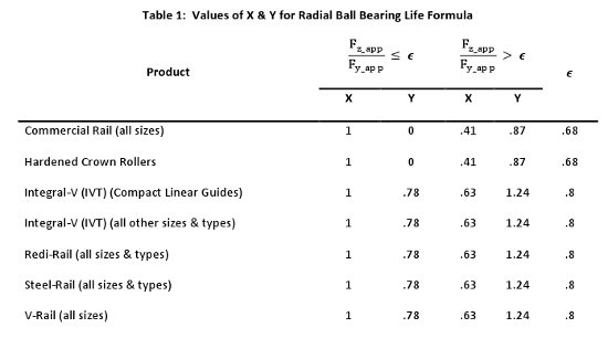
The values for X & Y can be found using the following table.
Individual Rollers – Hevi-Rail Rollers
Hevi-Rail bearings are roller bearings, as opposed to radial ball bearings. The formulas are very similar to the formulas shown above, with only some minor changes.
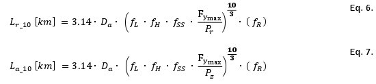
NOTE: Hevi-Rail rollers are combined bearings. Essentially there are two bearings combined into one. Life calculations should be performed for both the radial and the axial bearing.
Carriage (Slider) Assemblies
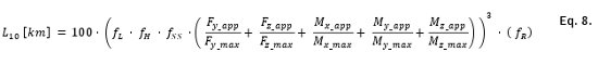
Formulas for calculating the estimated lifetime for carriage assemblies are fundamentally similar to the calculations for the individual rollers. The most accurate method for determining the life of a carriage (slider) assembly is to create a free body diagram for the carriage and determine the axial, radial and moment load applied to each individual roller. This method is cumbersome and is usually only required in the most severe of circumstances. In most cases, the carriage (slider) assembly can be treated as a rigid body and calculations can be completed based upon the load ratings for the entire carriage (slider).
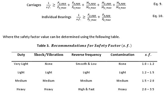
Safety Factor
All individual rollers and carriages are subject to use a balancing formula which ensures an adequate product life. The following formulas should be used for all CRT Products.

NOTE: The table above contains suggested safety factors based upon the most commonly encountered adjustment criteria. Additional criteria may require raising the safety factor.
Minimum Load Notice
It is possible to apply too small of a load to a bearing/carriage. In this case, there is a possibility of the outer ring slipping or the roller lifting off the track. This can cause unexpected vibration or skidding which will reduce the life of the bearing. Therefore, the following condition should be met under dynamic load conditions.
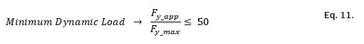
There is no minimum load requirement under static conditions.
Heavy Load Notice
It is also possible to overload the bearings. Extra-heavy loads can cause unexpected stress concentrations in the bearing or railway which reduce the actual lifetime below the minimally acceptable level. These stress concentrations typically come from unexpected vibration within the application or unexpectedly high preload forces caused by misalignment, damage or thermal expansion. In these cases, a larger safety factor should be used.

NOTE: Although typically applying to linear motion rolling bearings, ISO 14728-1 states that the above equation should be followed. It should be treated as a rule as opposed to a guideline.
If the product under consideration is a carriage (slider) assembly and Pr > 0.5•Cr, then it is recommended to consider the axial, radial and moment load applied to each individual roller to ensure each roller still has an adequate safety factor.
Shaft/Rail Hardness Factor, fH
It is possible to use a softer rail material in combination with PBC Linear’s CRT products; however, it is necessary to reduce the static and dynamic load capacities of each product. The reduced load capacity is known as the Effective Load Capacity. This value can be calculated using the formula below. The reduction factor, fH, can be determined using the figure below.
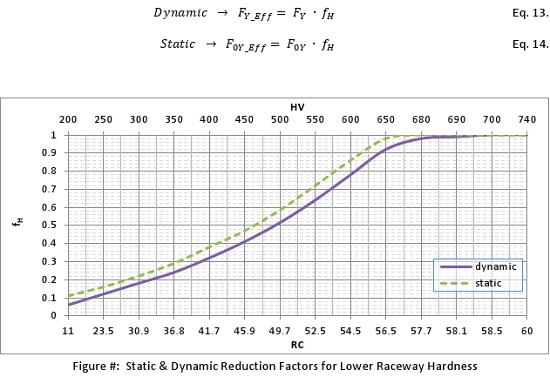
For easy reference, some of the most common materials have been plotted on the on the chart above. The circled numbers correspond to material types listed in the table below. Other material types can be used.
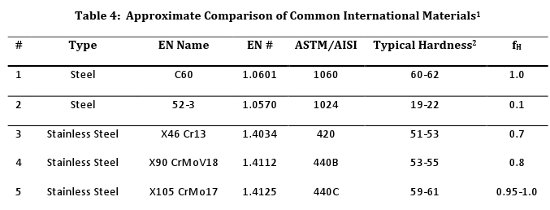
1Material Types may not be an exact match. PBC Linear has carefully reviewed the material standards and has determined that if there is not an exact match; the listed materials are the closest approximation. A material specialist should be consulted before translating one material type to another.
2Different suppliers may have alternate ranges for material hardness, depending upon their heat treating process. Consult manufacturer’s specifications for a more exact number/range.
NOTE: The values listed in the above table should be considered for reference only. It is critical that individual suppliers are contacted to ensure an accurate hardness rating. Depending upon the supplier, hardness can actually be the minimum, maximum, or average value. The wrong interpretation can have unexpected consequences for the application. When given the choice, PBC recommends using the minimum hardness when determining the reduction factor as this is the most conservative method.
Required Lifetime (km) Factor, fL
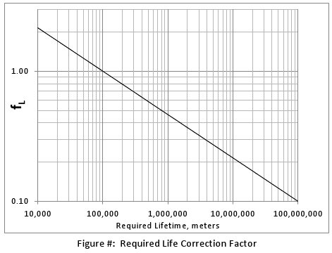
The standard lifetime formulas listed within this catalog describe an L10 life based upon 100 km, in accordance to the applicable ISO standards. Sometimes 100 km is either excessive or shy of the target life of a machine and the required lifetime needs to be adjusted. An appropriate adjustment factor can be found using the chart, below.
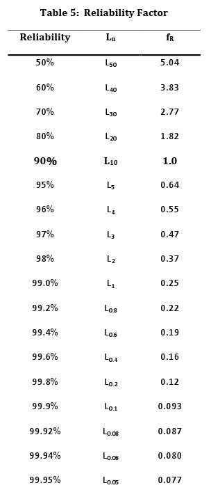
Reliability Factor, fR
The L10 Life Formulas are a statistical probability formula with a success rate of 90%. Sometimes an L10 life (90% success) is just not good enough and the formulas need to be modified in order to have a higher probability of success. In this case, choose the desired reliability rate and insert the fR value into the life equation.
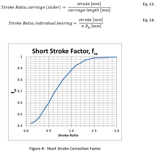
Short Stroke Factor, fSS
In the case that the travel distance is low, a short stroke reduction factor must be included. In general, this factor only applies when the stroke is less than 2x the carriage length. In the case of individual bearings, use 2 full revolutions of the bearing.


