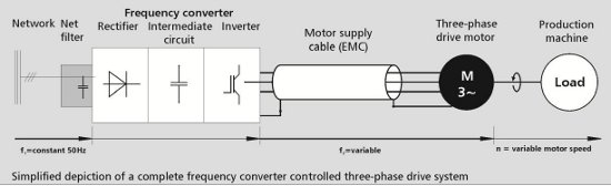
Electric drive systems with continuous torque and speed control are widespread today. They allow an optimal adjustment of the drive with respect to the application. Standard drive systems consist of 3-phase, alternating-current, asynchronous motors and related controls via frequency converters.
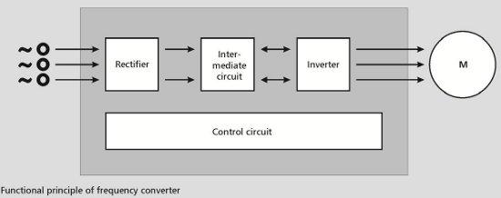
A frequency converter consists of two Insulate Gate Bipolar Transistor (IGBT)-controlled units:
a rectifier that is connected to a 3-phase, alternating current with a given frequency f1 (e.g. 50 or 60 Hz), which generates a pulsating direct current; an inverter that reconverts the direct current in a new alternating voltage with variable level and frequency f2 (0 to 400 Hz). Using the motor supply cable, the speed of the servo motor can be precisely controlled by changing the frequency f2.
Negative Effects
The benefits of frequency converters – precise and continuous variable torque and speed control – come along with certain negative effects that should be taken into consideration:
Strong electromagnetic interference through the motor power supply cable High overvoltage in the supply cable High leakage and interference currents
The strong electromagnetic interference results from the extremely short turn-on and turn-off-times of the IGBTs (nanoseconds) and from the high pulse frequencies of the frequency converter (up to 20 kHz). This leads to a very high proportion of harmonic waves of the sinusoidal output voltage of the converter. The strong electromagnetic emissions, emanated especially from motor supply cables, result in major interference with the distribution network, the devices, and data transfer.
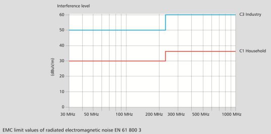
As a consequence, the European standard EN 61 800-3 (July 2005) specifies the maximum interference level of drive systems in order to ensure that signal transmissions are adequately protected against interference. This regulation, which differentiates between category C1 “residential areas” and category C3 “industrial areas,” establishes the maximum permissible interference levels of the radio interference voltage from 0.15 MHz up to 30 MHz, and of the radiated electromagnetic interference from 30 MHz up to 1,000 MHz (1 GHz).
However, interference can be avoided if well-shielded cables and, in special cases, cables with additional line filters are used.
Problems with Electrical Surge
The voltage generated by the frequency converter has a fundamental wave with an approximate sinusoidal course and an impressed frequency between 0 and 400 Hz, depending on the set motor speed. That process also creates harmonics in a high frequency range of approximately 100 MHz. The fundamental wave and the harmonics are transmitted to the motor via the motor supply cables.
When the characteristic impedance of the motor supply cable is changed, impulse waves are generated at the beginning and end of the cable, which in turn generate electrical surge through reflection of the harmonics (called reflected wave phenomenon). This only occurs if the length of the motor supply cable is greater than the wavelength of the harmonic. With short cable lengths, i.e. if the cable length is shorter than the wavelength, transient responses appear at the frequency converter output. As a result, voltages are generated that are two to three times greater than the motor voltage. Those voltage peaks place a recurring load on the insulation of the motor supply cable. For this reason the insulation must be dimensioned in such a way that those voltage peaks do not have any harmful effects (e.g. failure of cable due to arcing between conductors to shield).
The high frequencies at the converter output mean that high capacitance leakage currents are generated, which flow over the shield and the motor housing to the earth, and thus determine the cross-section of the braided shields and the shield connections. The shield must be designed in such a way that it is not excessively heated by the current flowing through it. Especially with long cable lengths, high earth capacitance can result in reactive currents, which burden the frequency converter. Due to the inverter's overcurrent limit, it might no longer be possible to transmit the necessary active power to the motor. Adequate care must also be taken to properly ground these currents and not change the voltage potential, which will affect the clock timing. Using a HELUTOP® EMC cable gland and attaching the cable ground wire to the panel bus ground terminal are good practices to help prevent this problem.
The reactive current does not contribute to torque generation at the motor and flows to the ground as current leakage via the shield and metallic motor parts. It can also flow through the ball bearing of the motor shaft, which can result in damage, such as depressions in the ball bearing rings.
In order to compensate for the above-mentioned effects of frequency converter technology, Helukabel® offers motor supply cables with optimized characteristics. Both the material used and the design are specially adapted for this application.
Helukabel® TopFlex®-EMV UL/CSA
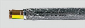
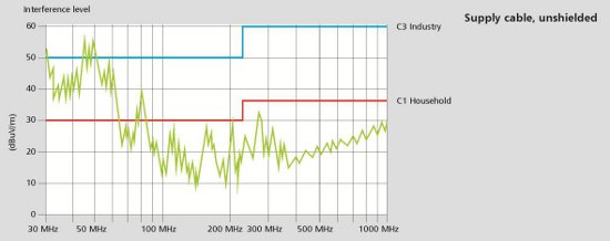
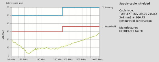
The electromagnetic compatibility (EMC) requirements according to EN 61800-3 are fulfilled by a double shielding of special aluminum foil and an optimized braided shield of tinned copper wire with a high degree of coverage (approx. 80%). The special suitability in the frequency range from 30 to 1,000 MHz is easily demonstrated using comparative measurements of the radiated electromagnetic noise from unshielded power supply cables and shielded EMC power supply cables from Helukabel®. For the low frequency range of 1 MHz up to 30 MHz, the high interference protection is shown by the extremely low coupling resistance of the shielded cables.
EMC Tests on Motor Supply Cables
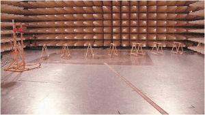
The measurements were made in an EMC laboratory
The results of the interference level measurements show clearly that the Helukabel® motor supply cable with an optimal shield did not exceed the limit values for interference field strength according to EN 61 800-3. Moreover, the interference field strengths of the unshielded cable are significantly above the limit values for industrial and residential areas, especially at low frequencies.
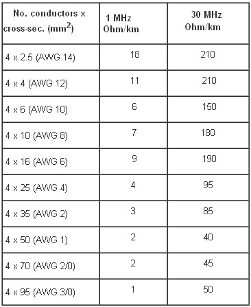
Results of Measurements of the Coupling Resistance Rk (Ohm/km)
Cable type: TopFlex®-EMV 2YSLCY J 0.6/1kV
Manufacturer: Helukabel® GmbH
In the low frequency range between 1 MHz and 30 MHz, a low coupling resistance was measured, resulting in low interference field strength in the surrounding area.
The conductor insulation of TopFlex®-EMV and TopFlex® MOTOR-EMV cables consists of electrically high-quality materials based on polyethylene (PE). The special insulation is designed for the permanent voltage peaks of the converter's nominal voltage.
Nominal voltage: Uo = 600 V
Max. permissible operating voltage: Ub = 1200 V
The frequency converter output can also be equipped with an electrical filter which filters out the high-frequency harmonics and smooths out the voltage peaks.
Impedance Matched Cables
Due to the low dielectric constant of the special conductor insulation, the TopFlex®-EMV and the TopFlex® Motor-EMV have a lower operating and shield capacitance than traditional PVC-insulated motor supply cables. As a result the capacitance disturbance currents are considerably reduced, enabling low-loss power transmission from the converter to the motor. Moreover, the high quality of the cable insulation provides a long service life. These characteristics are further improved by a symmetrical cable structure with three balanced power conductors and a ground conductor which is divided into thirds (3 + 3 -conductor design) in the cable types TopFlex®-EMV 3 Plus and TopFlex® Motor-EMV 3/3 cables. This results in an additional optimization of the power transmission from the frequency converter to the motor.
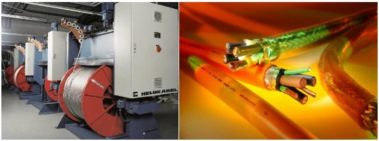
Reeling after braiding at the Helukabel® factory; Helukabel® TopFlex® Motor-EMV cable
TC-ER and Continuous Flex Applications
In addition to high-end motor cables, Helukabel® offers a wide range of tray-rated cables according to UL 1277, NFPA 79 2007, and CSA FT4 for fixed or continuous flex applications. The TrayControl 600 and TopServ 600 VFD cable possess a superior oil performance of Oil Res I and II and are designed for use in dry, high humidity, and damp environments and in the open unprotected installation in the cable tray or track.


