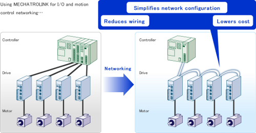
Field networking, such as EtherCAT, POWERLINK, CANopen, and MECHATROLINK, are growing in popularity, replacing traditional motion control communications such as ±10 V, or pulse trains. In the diagram below, the left side represents Analog Network System (traditional) and the right side, Field Network System (modern).
When noise affects a field network line, or if sources of latency affect the network line, the consequences are typically a dropped packet. Motion field devices for positioning like the Yaskawa servo drive will typically linearly extrapolate the next data point based on the previous 2 data points, to determine where the position of the motor should be, when a data packet is dropped.
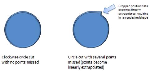
Enough dropped packets in a short amount of time (such as 3 consecutive missed packets) can result in the field device throwing an alarm. This results in stopped motion, otherwise the machine could produce undesired parts. An example would be cutting a circular shape, and missed packets would result in linear extrapolation, so the circle is no longer circular.
When users see these kinds of alarms, the machine panel that contains the devices is usually already built, and the devices were not installed or used exactly as specified by the device user's manual. Some situations users might find themselves in include that no major redesigns can be performed within the project timeframe, and thus a quick fix is sought instead of redesigning the panel to install the devices according to the device user's manual.
This article describes several quick fixes that may help in such situations. An important idea to keep in mind is that some of these quick fixes are counterintuitive, like using non-shielded cables instead of shielded cables. This is because a system that has devices already installed but not according to the device manufacturer's recommendations has an unknown noise immunity profile.
Beginning the Troubleshooting Process
The first step in this troubleshooting process is to find a way to determine what quick fixes are helping and which are not.
One way is to find a dropped packet counter implemented by either the master device or slave device. In the Yaskawa EtherCAT drive, there is a Sync Error Counter that increments every time a packet is dropped. By checking this monitor, a user can determine how much faster or slower this counter is increasing, and thus can determine if the quick fix is helping or hindering the dropped packet rate.
If the counter is not available, consider modifying the master application code to perform its own counter, checking if response data arrived from the field device.
If modifying the master application code is not a feasible option, then find the consistency of how often the alarms appear on the drives, and check if the alarms occur sooner or later as the quick fixes are implemented.
The Second Step
The second step in troubleshooting is to check for wiring mistakes and communication setting incompatibilities. There is a distinction between the specifications of the network itself vs the implementation of the network in the field device, which can result in communication incompatibilities. Here is a list to check:
- Check the user's manuals of all the devices on the network to determine if they support the network communication cycle time that the master is using. For example: Ethernet-based networks can operate at 31.25us, but not all devices on the network can operate at that rate. 125us is the fastest communication cycle time for servo drives in today's industry, which is a rate supported by Yaskawa's servo amplifiers.
- Check the user's manuals of all the devices on the network to determine if there are any communication cable length restrictions. Ethernet-based network vendors publish 100 meters for the communication cables, but not all devices are capable of being connected with 100 meters and still maintaining a usable signal.
- Check the communication cable wiring, such as plugging the communication cables into the correct ports (from one device's OUT port, to the next device's IN port).
- Check if termination resistors are needed, and install them. Networks like CANopen require a termination resistor at the start and end of the network.
- Check the network's installation specifications to determine if a repeater is necessary, and check if the number of devices on the network exceeds the maximum allowable devices. In some networks, a repeater is needed to achieve the published maximum number of devices allowed for the network.
The Third Step
The third step is to implement the quick fixes. There are two types: those related to noise, and those related to latency. Here are quick fixes that have helped in the past:
Latency-related quick fixes
1. If the master is PC-based, closing some PC programs may allow the processor to use more time for the network communications. Increasing the priority of the communication task may also help.
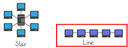
2. Remove network hubs from the network by changing the topology to line topology. COTS network hubs are not always designed for industrial network communications, and add network latency. Even industrial network hubs may cause packets to drop if not installed properly because of noise, so taking network hubs out of the system may help the network communications.
3. Increase the communication cycle time in the master. Setting a longer communication cycle will give a larger window for a packet to arrive on time and not be considered dropped.
4. Check the communication cycle time in the master. In some cases, the base time of the master is 0.333 microseconds, and the master will use a multiplier of the base time for the communication cycle. In this example, if the multiplier is x3, then the communication cycle ends up being 0.999 microseconds, which is not the same as 1.000 microseconds. In this case, the base time can be changed to 0.250, with a 4x multiplier for communication cycle.
5. Change the network clock method. In some networks, like EtherCAT, there are different methods for clock synchronization, including using the master as the network's reference clock, or using the first slave on the network as the network's reference clock. Using the master as a reference clock can cause network latency, especially if the master is performing multiple tasks such as being used as a general PC. Switching the network clock method to use the first slave on the network as the reference clock may improve the synchronization of the network, reducing network latency.
Noise-related quick fixes
6. Switch to shielded communication cables or non-shileded communication cables. Many field networks are Ethernet-based like EtherCAT, POWERLINK, and MECHATROLINK. Shielded Ethernet cables are readily available COTS (Commercially off the shelf, like at local electronic stores). If shielded communication cables are used, but were made in-house, check that the shield is connected to the metal part of the connector, otherwise the shield is not grounded. In some cases, changing systems with shielded cables to non-shielded cables improved the network communications.
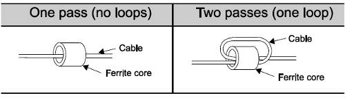
7. Use of ferrite cores on the communication cables. Two passes (one loop) through a ferrite core compared to one pass through a ferrite core can make a difference. Putting one core on the cable versus putting one core on each end of the communication cable can also make a difference.
8. Length of communication cables. Since noise is not always easy to characterize, using shorter cables may help, but on the contrary, using longer cables may also help. Ether can be tested in a situation for a quick fix.
9. Route the network cables away from cables that carry power. Power-carrying cables or conductors, such as main power or motor power cables, can cause interference to network cables. The network cables should be separated at least 30 cm from power-carrying cables or conductors.
10. Enable communication data retries in the master. If the network supports resending dropped data within the communication cycle time, or "data retries," then enabling this in the master gives dropped data an additional chance to be transferred. Networks like MECHATROLINK support this feature built into the network, so all MECHATROLINK masters are capable of easily utilizing this feature.


