Steven Elliott, Plant One Manager, OEP Couplings, div of Oren Elliott Products, Inc.
When selecting a shaft coupling, a large number of factors need to be considered, and many of these factors interact with one another, further complicating the task. For example, an engineer might want the coupling to absorb torsional vibration; but this will inevitably cause the coupling to have a lower torsional stiffness, and couplings with elastomeric elements capable of torsional dampening typically exert large reactive forces on support bearings if forced to accommodate large radial misalignments. The engineer will have to prioritize each of these factors in his application, and may be required to compromise on some or all of these characteristics.
In general, the engineer will have to make the following choices in specifying a shaft coupling:
Type of coupling: The engineer will have to select the general type of coupling based on each type's strengths and weaknesses, and based upon the general requirements of his system as he has prioritized them; Size of coupling: This is driven primarily by shaft size and by the torque requirements of the system, but it also impacts misalignment accommodation, rotational inertia, and cost. Material: This will affect the coupling's torque rating, mass, and cost, as well as other factors. Bore types and shaft attachment options: Bore selection is typically driven by the shafts involved; and attachment options require the engineer to balance cost versus serviceability. Other factors that might be unique to the system, like dynamic balance of the coupling at high rpm.
In each case, the engineer must balance cost of the coupling, performance and life cycle of the coupling, and the priorities lent to each performance criterion for the application.
Type of Coupling
In some situations, it will be obvious what type of coupling is needed; for example, if there is no significant misalignment, then a rigid coupling will be the least expensive and most reliable choice. If torsional dampening is clearly the primary consideration, then a jaw coupling is the obvious choice. But in most situations, the engineer will have a set of system requirements that will require balancing many different factors and making choices that prioritize those he considers most important, while compromising on other factors. These considerations include:
Torque requirements of the system: Torque requirements can be calculated from either the torque of the driven component or from the horsepower and rpm of the driving side. However, service factors related to the nature of the application should also be considered, and the coupling should be derated for temperature and misalignment if either approaches the operational limits of the coupling.
Total service factor is the sum of the driven side's service factor and the driving side's service factor, and each is a measure of the severity of the application. Specific service factors for various applications are listed within OEP Coupling's Part Number Selection Tool. This tool also rates the coupling for temperature and misalignment: even though a coupling might be rated for 180°F, this doesn't mean that its performance at 170°F will be the same as it will at room temperature.
Torsional vibration dampening vs torsional stiffness: As one increases, the other decreases.
Misalignment of the system: Radial, angular, and axial, after any possible thermal expansion during operation.
Reactive forces exerted by the coupling: Under misalignment, all flexible couplings exert reactive forces on the support bearings in the driving and driven components; the size of these forces varies with the amount of misalignment, the amount of torque, and the type of coupling.
Coupling performance vs coupling cost: In some situations, the value or fragility of driving or driven components will compel the designer to spec a more expensive coupling that exerts smaller reactive forces, for example.
Coupling lifetime vs cost of replacement: In some situations, when downtime of the device is particularly expensive, or when the design of the assembly makes servicing the coupling difficult, the engineer will select a coupling that's less likely to require replacement or service.
Different types of couplings offer different advantages and disadvantages.
Rigid couplings can accommodate almost no misalignment; should some misalignment occur, from assembly inaccuracy or from thermal expansion during operation, the use of rigid couplings can result in large reactive forces on support bearings. However, when these misalignments are small and these bearings are stout, rigid couplings will be the choice for both lowest cost and longest life.
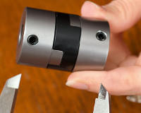
Oldham couplings can accommodate large radial, small angular, and moderate axial misalignment; they offer good peak torque rating and torsional stiffness, homokinetic transmission (the driven side moves at the same speed as the driving side at all times), very low reactive forces, and low cost, and are a good all-around choice for a flexible coupling in most applications.
Oldham/universal couplings offer all of the advantages of Oldham couplings, but can accommodate up to 6 deg of angular misalignment.
Block couplings are an older variation of the Oldham coupling that don't offer the Oldham's mechanical-fuse midsection: under excessive torque, an Oldham coupling's midsection will break, but the hubs remain intact, so the inexpensive midsection can be replaced. A block coupling won't break until the hubs themselves fail also. (The block's midsection can be replaced after wear, however). This fail-safe feature might be considered advantageous in some applications. The block coupling can include an internal grease reservoir, and is good for harsh or dirty environments.
Jaw couplings offer the advantage of torsional vibration dampening. They accommodate large torques and small misalignments with low cost. They don't have good torsional stiffness, however, as some windup will occur.
Universal joints are used in applications with very large angular misalignment -- up to 45 deg with a single joint. Radially and axially, however, they're essentially inflexible.
Magnetic couplings are used to transmit rotation across a barrier. They accommodate large misalignments, and serve as a sort of slip clutch, but are rated for very small torques, have very small torsional stiffness, and high cost.
Beam or helical couplings are moderate-cost one-piece flexible metallic couplings that have high reactive forces under misalignment and some windup (up to 7 deg); although they have no sliding moving parts, they will eventually fatigue and fail, and there is no inexpensive replaceable wear element.
Bellows couplings have a thin-walled flexible metallic element, and can accommodate large misalignments with low reactive forces, but are useful only for low torque, and have low torsional stiffness when measured at torques that approach the peak torque. Like the beam coupling, these are moderate-cost units that will eventually fatigue.
Gear, grid, and chain couplings are very robust designs meant for large shafts (over 2 in. in diameter), very high torques, and rough applications.
Pin-and-bushing couplings are large-diameter assemblies that accommodate small misalignments and offer small torsional dampening.
Size of Coupling
Coupling size must be large enough to accommodate both shafts. A coupling can also be too large for a given shaft size -- for example, few manufacturers produce a 2 in. diameter coupling that can accommodate a 0.125 in. diameter shaft.
As coupling diameter increases, rated peak torque also increases, as does radial misalignment accommodation, so increasing the size within a given type is the most natural way to spec a coupling that will meet these two requirements. However, the engineer wouldn't want to overcompensate here and select a coupling that's larger than needed, as this would needlessly increase rotational inertia and cost.
Coupling Materials
Proper selection of materials can ensure that the coupling withstands the required temperature and torque, while minimizing cost. Rigid couplings, and the hubs of flexible couplings, are typically available in aluminum, stainless steel, alloy steel, brass, and advanced thermoplastics. Each has advantages.
Aluminum offers low cost and low moment of inertia. When coated appropriately, it also boasts low coefficient of friction, good wear characteristics, and good corrosion resistance. In couplings that don't have a sacrificial midsection -- so the strength of the hub is critical -- the use of proper alloys (like 7075) can make aluminum hubs as strong as alloy steel and almost as strong as stainless steel. For most applications, aluminum is the best default choice for metallic coupling components.
Stainless steel offers good corrosion resistance and high strength over a wide range of temperatures, but increases cost.
Alloy steel and brass are worth considering when cost is the primary consideration.
Ultem© can be used for rigid couplings, making them electrically insulating, with good strength at a wide range of temperatures and good dimensional stability.
Several options are also available in the midsections of flexible couplings:
Delrin© is the most common choice for non-elastomeric flexible couplings like the Oldham coupling. It offers low cost, good wear, relatively high torque and torsional stiffness. There is a major difference in performance, however, between machined Delrin midsections, which offer higher static break torque and torsional stiffness, compared to cheap molded Delrin midsections.
Nylon is sometimes offered in Oldham couplings as an even-lower-cost alternative to Delrin; it's also sometimes billed as having more torsional dampening than Delrin, although any difference between the two in this regard is negligibly small.
High-temperature thermoplastics are sometimes offered as an alternative to Delrin; they exceed Delrin not only in maximum service temperature, but usually in torque and stiffness as well.
Urethane is a common choice for the midsections of elastomeric flexible couplings like the jaw coupling, with good all-around performance in terms of compression set, wear, service temperature, and chemical resistance. OEP Couplings also offers their Oldham coupling's midsection in urethane, coated with a low-friction coating; this provides the user with a hybrid coupling with the large radial misalignment accommodation and low reactive forces of an Oldham coupling, but with excellent torsional dampening characteristics.
High-temperature molded rubbers are sometimes offered as an alternative to urethane for jaw coupling midsections.
Bore Types and Shaft Attachment Options
Bores can be polygonal, to fit polygonal shafts, but cylindrical bores are the most common. There are three types of cylindrical bores.
Through-bores are the most common option; they have a big advantage in ease of mounting, because the hub can be slid back over the shaft and out of the way to insert the midsection, then slid back and locked down, so that the coupling can be installed without moving either the driving or driven component.
Blind bores (bores that don't go all the way through the hub) offer the potential advantage of giving a bottom of the bore for the shaft to push against, helping to axially locate the hub relative to the shaft.
Keyed bores can be either through-bores or blind bores. A keyway is broached into the bore to accept standard inch or metric keys that also seat in a keyway in the shaft. This helps to transmit torque from the shaft to the hub, preventing shaft slippage, even at very high torques. This adds to the cost of the hub, and it means that the angular position of the hub relative to the shaft is then predetermined and can't be adjusted.
Shaft attachment options include:
Set screws are the least least expensive and most versatile shaft attachment method; but they can mar the shaft, making removal difficult.
Clamping mechanisms are non-marring, making it easy to replace the midsection, and provide high shaft-locking torque, particularly when combined with a keyed bore.
Pins can be inserted through a cross-drilled hole in the hub and a hole in the shaft. This makes removal difficult, but not impossible, and is a common attachment method with universal joints.
Other Considerations
A factor that the designer would have to consider in very high rpm applications is coupling balance. At high rpm, an unbalanced coupling can cause large forces on the support bearings, and can cause vibration. Most couplings are supplied unbalanced, and can be supplied balanced at an additional cost. Many couplings are supplied very far out-of-balance, with set screws or clamping screws on just one side of a hub, and no features to provide symmetrical weight distribution.
OEP Coupling's designs are all at least theoretically symmetrical in weight distribution, so that even without the additional cost of balancing on a balancing machine, they will be closer to being balanced without this additional step than those of other manufacturers.
Occasionally, reactive forces or vibration from flexible couplings will amplify other forces within the system, or create a feedback loop and amplify themselves at certain critical frequencies. This is difficult to predict, and experimentation is usually necessary to determine if this will happen. Often this situation can be alleviated by using different hub materials with different masses.
Conclusion
After choosing a type appropriate for the application, a size that will fit the shafts and that has adequate torque, appropriate materials, and the best bore types and shaft-locking features for the application, the designer should verify that his selection meets any of the following criteria that are considered critical:
The torque rating of the coupling exceeds that of the application, based on torque of the driven component, or based on horsepower and rpm of the motor, after considering service factors, and after the coupling is derated for temperature and misalignment (if either approaches the operational limits of the coupling); The coupling is rated at or above the rpm of the application; The coupling is rated at or above the anticipated shaft misalignment (radial, angular, and axial), after any thermal growth during operation is factored in; The coupling is rated above the anticipated maximum ambient temperature; The coupling can physically accommodate both shafts, and fits within the physical envelope available, including coupling length, coupling outer diameter, and bore depths; The coupling meets all design criteria in terms of torsional stiffness, rotational moment of inertia, torsional dampening, dynamic balance, and harmonic stability at all frequencies that it might encounter; The coupling's cost is within budget.
Most coupling manufacturers have a technical staff capable of assisting designers in coupling selection.


