An Overview of Rolling Resistance, How to Calculate, & Apply to Industrial Wheel Applications
Friction plays a major role in the industrial world, and also in everyday life. Friction is the resistance to sliding, rolling, or flowing motion of an object due to its contact with another object. It can be either beneficial (when we brake our car to stop) or detrimental (trying to drive with one foot on the brake pedal). This article will focus on rolling resistance, an important facet of industrial wheels.
Rolling resistance is a measure of the retarding effect of a floor surface at the tread/floor interface of the wheels. It is normally expressed in pounds and is a measure of the energy dissipated per unit of distance rolled. Consider a tire rolling on a flat surface. The tire will deform to some extent, and that deformation will cause some resistance to the rolling motion. The flat surface may also deform, particularly if it is relatively soft. Sand is a good example of a soft, rolling-resistant surface. Bicycling across a paved roadway is much easier than across a white sandy beach. Rolling resistance measures the energy lost as something is rolled a specific distance.
In the world of industrial wheels, rolling contact would ideally offer no resistance to motion (except when we wanted something to remain in place). But reality doesn’t work this way. Energy is dissipated:
a. Due to friction at the contact interface
b. Due to elastic properties of materials
c. Due to roughness of rolling surface

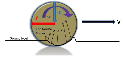
As one can see in this exaggerated view, both the wheels and the surface undergo deformation to the extent determined by the elastic properties of the two surfaces.
Rolling Friction vs Sliding Friction
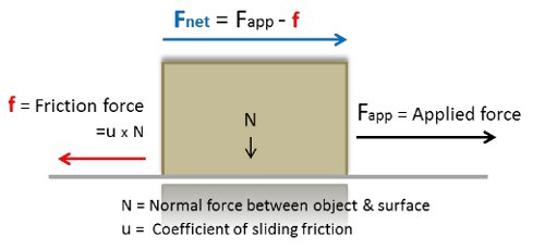
Coefficient of rolling friction should not be confused with coefficient of sliding friction or, as it is often called, the coefficient of friction. Coefficient of (sliding) friction is a unit-less number that describes the ratio of the force of friction between two bodies and the force pressing them together. The coefficient of (sliding) friction depends on the materials used; for example, steel on ice has a low coefficient of friction, while rubber on pavement has a high coefficient of friction.
The diagram below right addresses sliding friction. Imagine the force required to push a heavy box across a floor. Static friction requires a certain applied force to get the box moving. Once moving, dynamic friction requires a relatively constant force to maintain that motion. In this example, the person pushing is producing the “applied force,” and the box weighing “N” and the floor create the “friction force” which tends to resist that motion.

The reason we use wheels in material handling is the significantly lower effort (force) required to move an object. Imagine pushing a refrigerator or a piano without wheels! Furthermore, consider how much easier it would be to push the box (mentioned earlier) across the floor if it were on wheels.
The force required to push/pull wheeled equipment is always greatest at the start, just before movement begins. Ergonomists refer to this force as the initial or starting force. Fortunately, the initial forces typically last only a short time and drop to the sustained force levels once the acceleration begins and any mechanical interference at the start of movement is overcome. Once in motion at a relatively constant speed, the force requirement is generally lower. This force is called the sustained or rolling force.
Calculating Rolling Force
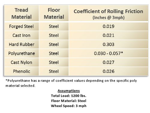
To help quantify rolling resistance in industrial wheels, there is the coefficient of rolling friction. This is a number that has been empirically determined for different materials, and can vary by the speed of the wheel, the load on the wheel, and the material the wheel is contacting. In the chart below, it is not surprising that the softest tread material (rubber) has the highest coefficient of friction, while the hardest material (forged steel) has the lowest.

The Formula
F = f x W/R
F = the force required to overcome the rolling friction
f = the coefficient of rolling friction (units must match same units as R [radius])
W = load on the wheel
R = radius of the wheel
Example: Find the force required move a 4,800 lb trailer equipped with 8 in. diameter polyurethane 85A wheels on a flat steel floor.
Step 1: Based on given load we can determine the load per wheel “W”
W = 4,800 lb/4 (wheels) = 1,200 lb on each wheel
Step 2: From the provided table find coefficient of rolling resistance “f”
f = 0.047(in.) [Note: Polyurethane has a range of coefficient values, depending on the specific material selected.]
Step 3: Knowing that the radius is ½ of the 8 in. wheel diameter.
R = 4 in.
Step 4: Calculating the force “F” required to overcome wheel rolling friction.
F = 0.047 x 1,200/4 = 14.1 lb (Note: this is for each individual wheel.)
Step 5: Calculating the force required move the specified loaded truck
The resistance per wheel is 14.1 lb. Since truck has four wheels, the total force to move (sustained motion) the truck is 14.1 x 4 = 56.4 lb.
Wheel diameter plays a significant role in the force required to move a load. In the example above, using a 16 in. diameter wheel (with a radius of 8 in.) would halve the required force. In fact, that is the pattern established by the equation. Every doubling of the wheel diameter results in only half of the force required to move the wheel or to sustain the motion.
The force to start (initiate) motion is in general 2 to 2.5 times the sustaining force. In the example above starting force is approximately 115 lb.
For Easier Rolling
To reduce the force required to overcome wheel rolling resistance, one can select a wheel with a lower coefficient of rolling resistance (for example, the forged steel wheel has coefficient of rolling resistance of 0.019 in.) or use a wheel with a larger diameter. Optimize by doing both – use the largest practical diameter wheel with the lowest coefficient of rolling resistance.
Wheel bearing selection in regard to rolling resistance is not as critical as the wheel material and diameter. Anti-friction bearings don’t make as big a difference to rolling resistance as factors such as wheel material and wheel diameter. However, bearing selection can be very important for other reasons such as load capacity, manual or towed operation, presence of shock loading or side thrusts, and desired maintenance. As one might suspect, a softer wheel tread material will generally result in greater rolling resistance than a very firm/hard wheel tread material.
Major Factors in Rolling Resistance
The most significant factors to be considered are:
• Load
• Wheel diameter
• Tread material/hardness
• Floor material/finish
• Floor conditions (roughness, cleanliness, slope, etc.)
Factors that can usually be ignored during calculations are:
• Bearing type
• Grease or lubrication effect
• Ambient temperature
• Wheel slippage
Ergonomic Guidelines
General ergonomic suggestions for maximum (manual) pushing forces can be found in interactive tables at the Liberty Mutual Manual Material Handling section of their website.
Interpreting Results
Using the calculator provided on that website will yield results suggesting the percentage of the population (male or female can be specified) that can safely perform a pushing or pulling task. Variables include the pushing or pulling force (which comes from the calculations described in this paper), height at which the force is being applied, duration of the push or pull, and the frequency. In general, any result that exceeds 75% of the female population will be appropriate for sound safety considerations. Specifically, using this as a guideline will prevent low back injuries to a significant degree. Of course, there is never a guarantee of back injury prevention.
General Recommendation for Manual & Powered Operations
1. Select a suitable wheel/tread based on the maximum load and floor conditions.
2. If resilient tread is selected, typically for floor protection purposes, consider:
a. Temperature range
b. Impact resistance
c. Moisture and water
d. Resistance to light, chemicals
e. Rebound
3. Select the maximum possible/practical wheel diameter.
4. Select a wheel with the lowest coefficient of rolling resistance.
5. Calculate the rolling resistance (keep in mind that at startup the force will be 2 to 2.5 times higher).
6. Use a safety factor when calculating required power for drive applications.
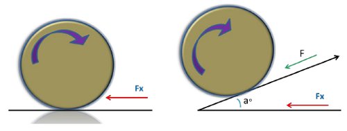
7. Remember to account for any slope present (a°). The calculated rolling resistance will increase up the slope and decrease down the slope (F = Fx/cosa). For example, a 10 deg slope will increase the required force (F = Fx/cos10° = Fx/0.9848 = 1.015Fx). If the slope is increased to 30 deg, the required force will increase substantially, from 1.015Fx to 1.155Fx (approximately 14%).

8. For powered towing operations, the wheel bearing selection is very important! Be sure to select bearings that will withstand the rigors of higher speeds, side load forces, and continuous duty.
Rolling resistance plays a major role in material handling. Whether loads will be towed or pushed manually, proper wheel selection will significantly impact the results. Using the principles described in this paper will enable good choices.


