Chaz Andrews Of Doepke Explains The Function Of The Solar Inverter Rcm Unit And Separate Rcd Protection Required Under The Wiring Regulations
Some installers are struggling to get to grips with the function of the RCM in a PV inverter and why you need a separate RCD on the output side of the inverter for specific installations. Incorrect specification and installation can lead to costly re-work for the installer, when the local DNO reviews the commissioning pro-form. DNOs have a legal obligation to ensure that PV installations do not pose a risk or affect supply quality.
To give a brief explanation of the function of these devices in a solar installation let’s consider a common installation example; a small scale embedded generator (SSEG) containing a transformerless inverter (TL) to be installed in private premises.
Basic Safety / Legal requirements covering SSEGs connected to the grid under G83/1-11DNOs/IDNOs have a responsibility to maintain the integrity of the supply in terms of quality and safety (ESQC 22& 26) with regard to the connection of SSEGs, hence the requirement for supporting documentation to confirm that they are meeting their legal responsibility. The installer signs a legally binding declaration to confirm that the installation meets the ENA’s engineering recommendations, including compliance with all of the relevant requirements of BS7671, required under ESQC 22(2). Users are required to maintain the equipment in safe working order.
Note 1: G83/1-1 is in the process of being reviewed at the time of writing this article – refer to Ofgem web site.
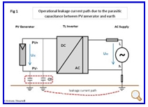
Operational leakage current paths for a PV SSEG containing a TL inverter (no galvanic isolation)
In fig 1 the TL inverter is connected to the main earth terminal on the AC side and as there is no galvanic isolation with TL inverter, the PV array and frame (generator) cannot be connected directly to earth2. Even though there is no direct connection to earth, the PV generator will leak current to earth under normal operation - parasitic capacitance creates a current path between the array modules/frame and Earth.

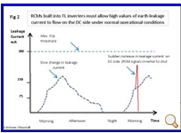
In addition to surface area of the PV array, the topology of the inverter will determine the level of leakage current that can be produced. The magnitude of this high frequency AC operational leakage current will change as a result of climatic conditions, moisture, dirt etc. on the surfaces of the PV generator. For instance in the morning it could be at its maximum due to overnight precipitation (measured values above 250mA) falling slowly as the modules dry out during the day. Without an isolating transformer, this represents a safety hazard – direct connection to the grid. For this reason following some accidents, TL inverters designed to EN standards have to monitor and react to sudden changes in the level of this leakage current produced on the DC side of the inverter, inbuilt RCMs carry out this function.
Note 2: Earthing; refer to the DTi PV installation guide and the SSEG manufactures installation instructions.
How does an RCM function ina TL Inverter with high levels of operational leakage current present?

The RCM unit built into a TL inverter is designed not to respond to slow changes in leakage current as these are expected in normal operation, unless the leakage current exceeds a predetermined level for instance 300 mA or if there is a sudden peak in the leakage current - see Fig 2. A sudden increase in leakage current indicates that something is creating a low resistance path to earth. In this situation the RCM should feed signals to the control section of the inverter, to indicate a fault condition /sound an alarm and disconnect the AC side of the inverter from the DC side. Disconnection is normally carried out by the same relay contacts used for interface protection with the DNOs distribution system. Don’t forget the PV generator is always considered to be energised irrespective of the operational state of the inverter.
RCD protection on the AC side of the SSEG
G83-1/1 requires compliance with BS767, so just a few general points to note here about the REGs relating to RCDs. Reg. 411.1 precludes the use of RCMs in the place of an RCD – “RCM is not a protective device” see note on page 52. RCDs are defined as protection devices, and come in two formats; RCCB manufactured to EN61008-1 and EN62423 if applicable and RCBOs manufactured to EN61009-1. Regulation 133.1.3 deals with the use of electrical equipment within its design limits, based on the appropriate standards and the responsibilities for specifying suitable equipment. Due to the safety implications and the legal responsibility placed on the DNOs, it is unlikely that they would accept the use of any equipment outside of the design limits defined in the associated product standard.
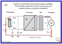
This is particularly relevant with regard to the correct selection of a suitable RCCB for use with a PV SSEG. Taking our example above, assuming an RCCB is required for fault protection, the operational leakage current is going to be significant (refer to the inverter installation manufactures guide). In this example to reduce the occurrence of unnecessary tripping during normal operation –REG. 531.2.4, we need to design our installation on the bases of using a 300mA trip rating.TL inverters do not meet the requirements for simple separation therefore a Type B RCCB is required – REG. 712.411.3.2.2.1.2. A word of caution on the note in the REGs, referring to inverters not feeding DC into the electrical installation - this is simplistic and creates a false sense of security for the installer. With existing PV technology it is not possible to guarantee that leakage currents with some DC content will not circulate within a PV system under certain fault conditions. In the event of an earth fault on the DC side of the system – see fig 3 the resultant leakage current waveform is complex. It will contain the following components; AC normally at 50Hz, DC and a HF component determined by the inverter topology and switching frequency and the DC voltage of the PV generator.

If the designer/ installer intends to apply this clause to support the use of Type A in place of Type B, (regulation 133.1.3) they need to be prepared to provide supporting evidence demonstrating that the DC content and shape of the waveform of the leakage current in their PV SSEG installation would not exceed the design limit given in the standard for Type A. Referring back to fig 1, the installation detailed will allow for significant DC leakage currents to circulate, anything above 6 mA (maximum allowed for Type A / EN61008-1) will have a detrimental effect on the RCD protection, due to the saturation of the sensing coil in an A type device. These risks have been recognised in Germany, where they have a long history with installed solar energy. The German insurance industry (vds_3145_web) specifies the use of Type B RCCB on all PV installations, where the manufacturer of the SSEG does not give information relating to the possibility of DC currents under fault conditions.
Installing an RCCB in an application were the standard design limits are exceeded would contravene regulation ESQC 22(2). Hence the reason for the specification and use of Type B RCCB’s in the UK.
Future Guidance
At the present moment many of the advice documents relating to this application area (PV) are in the process of being revised. Hopefully all the work being put into this area will result in clearer guidance for the industry and customers once the documents are published.
Installers who have to go back to site to correct their work, risk losing money on the job, credibility and the chance for positive references from the client for future installations in the local area.
Reference documents: G83/1-1 and G83/2, ESQCR Sec 22, BS7671 Amd.1 2011, DtiPV sys. 2nd ed. & 3rded draft, EN61008 & EN62423, VDS3145, FDIS IEC60364-7-712, Residual Currents in Photovoltaic Installations by S.Davids & G. Grunebast.
Author : Chaz Andrews – Technical Manager Doepke UK Ltd.


